Tuesday, December 4, 2012

Slow Going on the Restoration

Due to a busy work schedule, I have not worked on the Triumph that much in the past few months.  The progress that was made was due to hiring Central Mass Powdercoating restore the suspension parts.  Previously, I was in the final stages of restoring suspension parts myself (sanding off the rust and repainting), but after seeing how nicely the chassis turned out, I decided to get the suspension parts powdercoated as well.  The disassembly of previously assembled suspension parts was easy, however, the new rubber bushings were damaged during removal and I will have to get new rubber bushings.

Below are pictures of the suspension parts after being powdercoated.  The springs are powdercoated in red baron to match the chassis and everything else is powdercoated black with a gloss finish.  Total cost for powdercoating (suspension mounts, brackets, frames, springs): $450.

The powdercoated parts look so much better than the paint job I had done.

Wednesday, August 1, 2012

It looks AWESOME

The chassis looks AWESOME.  Jeff and company did a fantastic job bringing the chassis back to life.  It came out so much better than I thought it would and I'm really happy with the result.  Final cost for powdercoat and repair: $950.


This came out so well that I'm going to start disassembling previously completed suspension components to have Jeff and co. work their magic on those as well.  Can't have the chassis look good and the suspension mediocre, right?


Friday, July 27, 2012

Chassis update part 2

Jeff sent me a picture update on how the repairs on the Triumph were going and things are looking good.  I cannot wait to see the final results.


Monday, July 23, 2012

Chassis Update

Today I heard back from Jeff on the chassis and after coming back from sandblasting, they noticed 2 large rust holes and sizable dents on the outrigger part of the chassis.

Jeff offered services to straighten the bent mounts, cut out the rot, and fabricate new metal to patch the rust holes for $250, which I readily agreed to.  I figured that I was already getting the powdercoating done and this would make things look that much better...I've just got to ignore the fact that this will cost more than what I paid for the original car.


Tuesday, July 17, 2012

Off to powdercoat

Chassis strapped to Chris' truck for transport

This morning we dropped off the chassis at Central MASS Powder Coating to get powdercoated.  Jeff and company at Central MASS Powder Coating were super friendly and helpful in getting things squared away.  They took the time to explain and show what exactly would be done and helped me pick out "red baron" as the powdercoat color.  ("Red baron" is slightly brighter than the current chassis color, but when I'm done with the Triumph, I really want the car to stand out after all the time spent on it. :-) )
Leaving the chassis at Central MASS

Jeff also mentioned that if I emailed him a picture of any other car parts needing powdercoating, he'd send me a quote.  Given that the already restored suspension parts (that I had taken the time to sand and spray paint) are already chipping from moving them around the basement, I am considering taking him up on the offer.  At the same time, it feels like I'd be backtracking 2 years in my restoration effort to do this, but... long term, this would be the better thing to do.  (1 step forward, 2 steps back...)

The chassis should be ready in 1 - 2 weeks, so I'll post an after picture as soon as I can.


Monday, July 2, 2012

Awesome Triumph Engine Rebuild

Had to share this youtube video that Chris had found...  The video is comprised of 3000 pictures from an engine rebuild spanning 11 months!!

Great video...


Sunday, July 1, 2012

Ready for sandblasting and powdercoating

Back in spring, I had found and emailed a powdercoating company nearby about powdercoating the Triumph chassis.  Jeff at Central MASS Powder Coating in Clinton, MA emailed me back right away saying they could sandblast and powdercoat for ~$750.  The chassis just needed to be fully disassembled and basically degreased before I drop it off.  The shop would then sandblast, bake it out, mask all threads, and powdercoated with zink epoxy primer and then powdercoated with polyester taking about 1 week to do all this.  

Then work became busy again and summer weekends started to fill up, so I did not get a chance to ready the chassis for sandblasting and powdercoating until this weekend.  Despite the 90s temperature, the garage was bearable.  Chris helped to pull out the differential which came out pretty smoothly.  We used a jack to help support differential as the supporting bolts were removed and then a pry bar to dislodge the differential from the back mounts.


As for cleaning the chassis, I degreased years of dried, caked on grease with a can of degreaser, roll of paper towels, Q-tips (for those hard to reach places), and wire brushes.  I had started a bit of this previously but today I spent about 3 hours getting everything scrubbed. At the end of all this, I was covered from head to toe with grease bits that looked like freckles on my skin and had a mess of paper towels, Q-tips, and grease bits on the plastic tarp I lined the garage floor with before starting. 


Cleaning the chassis = the messiest I've been since this project started...

This used to be covered in grease...


Wednesday, April 25, 2012

These Brakes Need a Brand New Pair of Shoes

Picture post...

When the brake shoe pads fall off during removal of the brake drum, it is time for a new pair of shoes.

A side by side comparison of a restored rear brake assembly and unrestored rear brake assembly
.

So much easier the second time around

I'm happy to say that a task that had taken me 2+ weeks the first time around only took 30 minutes the second time. Progress was halted for 2 weeks the first time I tried to figure out how to remove a brake drum with a stuck brake drum screw. After going through the pains the first time, I realized the best way was to grind out the flared screw head using a Dremel. This would also etch the brake drum, but as I would be replacing the brake drum anyways, this was fine.

The screw holding the brake drums in place is actually a pretty soft metal. So after grinding most of the flared screw end out, pulling out the brake drum with the puller did the rest. All that was left to do afterwards was to use vice grips to remove the rest of the screw.

Caption: Using vice grips to remove the remaining screw end

Thursday, April 19, 2012

Pictures

Adding some pictures...

Back view of rear assembly. (restored assembly on right)

Picture of unrestored assembly...quite filthy. Everything is caked in grease so it is not too rusty.

I've also mastered the order in which bolts and parts should be removed and am down to the axle and drum by itself. Start by removing the radius arm and then vertical link to axle bolt. Having to break through the rust and filth, it took about 30 minutes to disassemble. (The vertical link to axle bolt was pretty corroded on the thread end making the nut removal difficult.)

Wednesday, April 18, 2012

Before and after rear assembly

To finish up the rear assembly, I punched out the old axle hub bearing seal (action picture on left) and replaced it with a new seal. I need to better organize the parts I order as I had to dig through old invoices and search around the house for the seal kit as I thought I bought it... then thought I might not have... and then realized I actually purchased the kit and had misplaced a whole set of parts ordered from Victoria British. Right now, there are car parts old and new throughout the basement, garage, and even parts of the living areas - keeping track of all this is getting to be difficult.

The new seal (picture of new seal and old seal is to the right) was easy to install and could easily be pushed in. Most of the remaining rear assembly components were easy to install except for when it came to wedging the radius arm into the vertical link. After the poly bushing is installed in the radius arm, there is hardly enough space to get it in position on the vertical link. Chris ended up taking a piece of wood to pry enough space in the vertical link arm hinge to get the radius arm in place. After that, we had to coax the bolt through the radius arm end since it was a tight fit and finally got through what would be the most difficult part of the night.

Then after getting everything in place, I realized I forgot to put a washer on the bolt that sits behind a vertical link/radius arm joint. (ugh) So we pried out the bolt then the radius arm and undid the bolt to install the washer. Reattaching the radius arm was much easier the second time around and now we are finally done with one of the rear assemblies.

Below shows the restored assembly with the brake drum absent (on left) with the unrestored assembly (on right).

Monday, April 16, 2012

Drum brakes ain't easy...

It wasn't easy, but one rear wheel restoration is almost complete. I made use of the 70+ degree weather we had this weekend to spray paint the rear brake plate. This was the last task needing to be complete before I could start reassembling everything.

It took a bit of picture digging and diagram studying to remember how everything fit together. It was clear on how to put most things back together as it fit well in a certain order or position. My d'oh moment of the night was when I forgot to put the key shaft (small metal piece that holds the hub and shaft in place) in the shaft before driving the hub down. Forgetting to do so and having tightened the hub down, I had to take out the hub puller and re-pull out the hub. (To see how to do this correctly the first time, skip to 7 min. 50 sec. in the youtube video posted on December 30, 2011.)

Putting in the brake components was a bit tricky as force and shuffling was required to squeeze everything in to place. Having Chris help me with this part definitely made things easier as one person could hold things in place while the other pushed and pull springs and other parts. Also, it helped to have another person to brainstorm ideas on how to put the pieces together. We learned that springs should go on early since they are on the undersides of the shoes, found it easier to put springs in place on the drums first and then position the drums, and that the shoe hold down washer/spring kit is more conveniently installed when using a wrench.

For the shoe hold down kit, in order to get the pin and washer aligned properly, we used the closed end of a wrench to push the washer and spring down while spinning the pin from underneath to lock at a 90 degree angle. The wrench opening allowed us to have a clear view to make sure we got the 90 degree angle. (Below: Chris using the wrench to push down the spring.)

There are still a few more things to put together on the rear assembly and then after that there is the driver rear assembly that needs to be restored. Almost one down and still another to go...(I'm a bit off track from my winter goal to be complete with both assembly units.)

Tuesday, April 10, 2012

Piece of cake

I put the shop press to test by swapping out the rusted and worn out wheel studs with new studs. From start to finish, this task only took 5 minutes with the new press. The press worked great and got the job done.


To support the extraction (and later insertion) of the studs, I used sockets to support the surrounding area under pressure by the press. The studs came out smoothly with the exception of one stud that had become rusted on over the years and came out with a loud bang. Insertion of studs was just as easy.


This picture shows the rust and grime from the stud that came out with a bang.


With new wheel studs all in place...


A treat...for myself

After a busy month at work, I decided to reward myself with a shopping spree at Harbor Freight and picked up a 6 ton A-frame bench shop press. It was something I had been considering to buy used off craigslist, but after no luck in my search and Harbor Freight having a sale, I splurged and bought a new press.

It was a bit of a pain to put it together by myself as it took some maneuvering to get all pieces to happily come together in some 3-dimensional shape. And then after all that effort, I still had to spend some time to get everything square before tightening all the bolts down. The paint job is sub-par as many parts show paint drips, but overall, the press is pretty sturdy and that's what really matters.

Up next, testing it out...

Sunday, April 1, 2012

If the wheel bearings are fine, I really really really should leave them alone


As I was typing the title in for this blog, the blogspot software provided an auto-complete option of "If it ain't broke...don't fix it". That blogged turned out to be related to replacing the front wheel bearings, in which I decided wheel bearings are better left alone unless broken. Clearly, I do not learn lessons well.

In the past month, I became so focused on removing the rear wheel bearing, since I had purchased replacement parts a while back and figured that since I have the replacement, I might as well use it. After trying to figure out how to gain clearance to the bearing, finding the jaw pullers to be inadequate for pulling the bearing, going to Harbor Freight to buy the bearing puller set that was current on sale for $39.99, FINALLY pulling the bearing off, but in the process grinding the axle head, I finally stopped and realized, "I really did not need to do this."

In the end, the bearing was fine, I didn't need to spend $39.99 and I could have moved along with the rear axle restoration without this step and saved hours worth of restoration effort. So now I think I have definitely learned this lesson, but just in case:
  • I will not replace wheel bearings unless they are broken.
  • I will not replace wheel bearings unless they are broken.
  • I will not replace wheel bearings unless they are broken.
  • I will not replace wheel bearings unless they are broken.
  • I will not replace wheel bearings unless they are broken.
  • I will not replace wheel bearings unless they are broken.
  • I will not replace wheel bearings unless they are broken.
  • I will not replace wheel bearings unless they are broken.
Just so this experience was not in complete vain, instructions on how to remove wheel bearings are below:

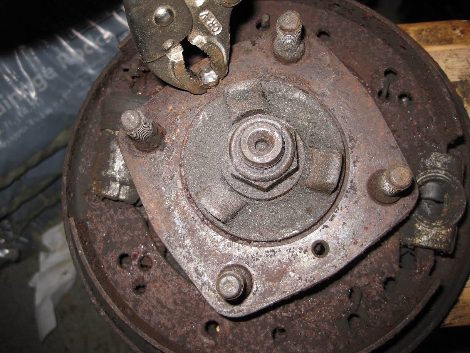
Step 1: Push the axle hub down using the rod and nuts method from Tuesday, March 13th's post. I went through a few rods getting bent in the process (fitting a nut on both top and bottom of the hub helped a bit). In the end, you just need enough space to slide the bearing guide plates in between.

Step 2: Assemble bearing puller around bearing. as you tighten the bearing plates, it will force itself to a better position by pushing the axle hub further down. (I spent too much time worried about spacing on the axle hub in step 1 and this step covered it.)
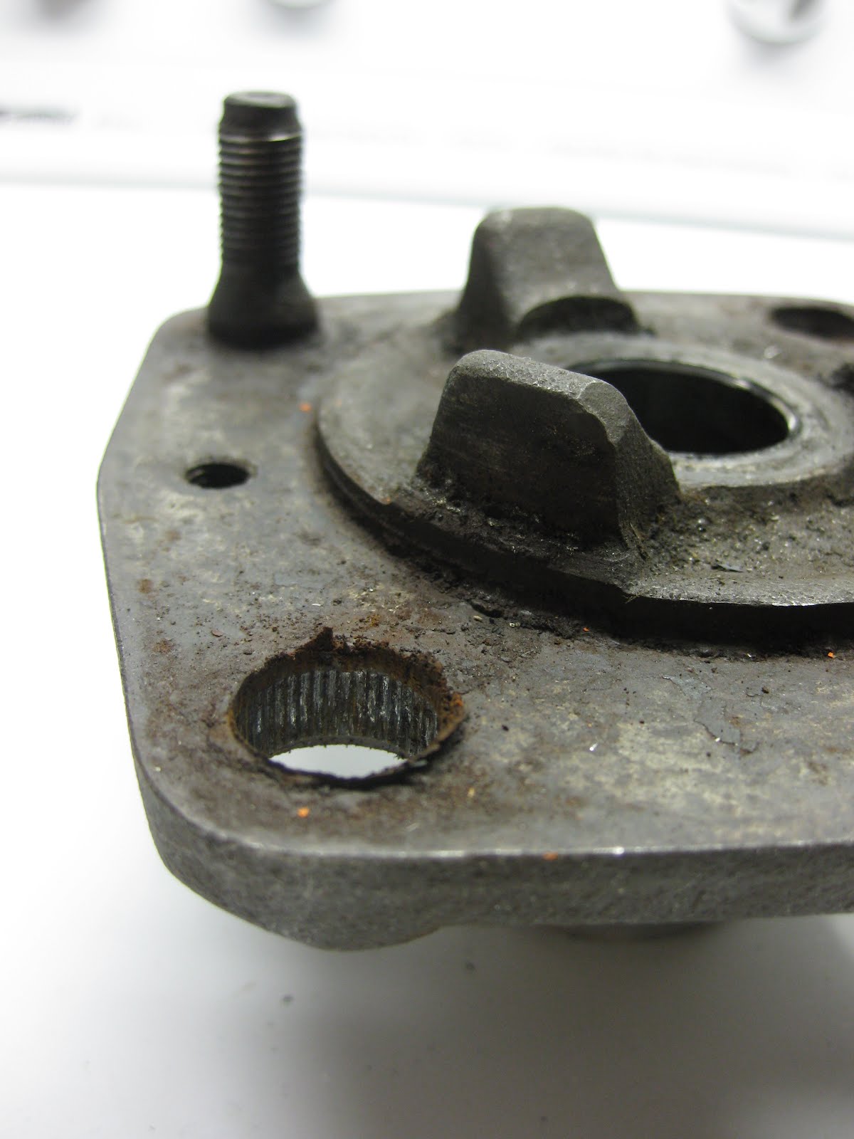
Step 3: Use something to protect the puller axles from the axle. I ended up grinding out some of the axle center before I realized this was happening and put a washer in between the axles.
(Picture on left shows metal shavings from the axle center.)

Friday, March 23, 2012

University Motors

During my youtube searches for how to do various car repairs, I stumbled upon University Motors. This shop, based in Grand Rapids, Michigan, mostly focuses on MG's, but their youtube postings offer a lot of information on British car repairs. They have tons of videos posted (193 as of 4/2/2012) and continue to add more.

You can check out their shop and latest projects/postings here:

http://www.youtube.com/user/Universitymotorsltd

Tuesday, March 13, 2012

An Electric Triumph Spitfire

I found this post on CNN and thought I'd share...

Dan Busby converted a 1964 Triumph Spitfire into an electric car using a 40-horsepower electric motor and 45 Lithium battery cells that take up the entire space under the hood and where the gas tank would be.

Too short, back to the store

I found this youtube video a while back while looking into how to remove the hub. It shows a quick and easy way to remove the rear axle bearing. The Haynes manual says to push the axle hub down the axle to get to the bearing, but with no further instructions than that. The video shows a cheap way to remove the bolts using threaded rods.

Using the same idea from the video above, I purchased some nuts and bolts to try and achieve similar results. Unfortunately, the bolts I purchased were too short. I was able to push the axle hub back, but the bolts were not long enough to fully expose the bearing. I ended making a second trip to the hardware store to get longer bolts to finish what I started. Re-watching the video again, I should have bought threaded rods.

My ineffective setup: (threaded rods that fit through the flange holes would have been better)

Sunday, January 15, 2012

Canley Classics


So I ended up ordering a hub puller from Canley Classics. I was planning to order the swing spring conversion kit at some point and figured I might as well get the hub puller while I was at it.

When ordering online with Canley, it doesn't tell you how much shipping would be and the exchange rate is approximate so it is hard to tell the total cost. That information came later after someone at Canley put together the order and emailed an order confirmation with the final price. Shipping for these parts came to 100 pounds which is much more than I thought it would be, but it did however come one week after ordering which was nice. The box arrived a little banged up, but everything came in good condition.

The hub puller is one solid piece of metal. The threads on the puller bolt make the Harbor freight jaw puller threads look puny. Even with the hub puller though, we still had a hard time pulling off the hub. We ended up using a 6 foot long breaker bar to get enough leverage to pull off the hub.

From watching the youtube videos of pulling hubs, I knew to expect a pop when the hub puller came off, what I wasn't expecting was what sounded like a gunshot when it did and so I ducked for cover when I heard that.

Gaining access to the hub space, the wheel bearings appear to be in good shape. The only items needing replacement are the hub gasket and the wheel studs, which is now do-able with the drive flange removed.

Making slow and steady progress...

Sunday, January 8, 2012

Researching for restoration

This weekend I didn't physically work on the car, but spent time researching next steps for the hub puller and then this lead to researching for a swing spring axle. I was considering to check with AutoZone if they had a universal hub puller in their loan-a-tool program, but after reading some online forums, I found that even this tool was not always successful when using to pull on a Triumph hub.

It seems that the best solution is to use a hub puller, similar to the one for sale by Canley Classics, a UK-based British car tools/parts supplier. Unfortunately the cost for this tool is $101 and to make matters worse, this tool is so specific, it does not even fit on all Triumph cars, like TR's. On a positive note, the tool is CNC from one piece of metal so it does appear to be good quality (no welds that could break).


While I was on this page, I remember that I had once considered using Canley Classics to buy a swing spring axle kit. This was something that I read on the forums to help with handling and keep the rear wheels from caving in when cornering. So if I buy the hub puller, I would get the swing spring axle kit at the same time.

I'm a bit disappointed that I couldn't rig my way out of this one with a tool I made myself, but after seeing how tight the hub is on by how it damaged the jaw puller, I think I may call myself defeated.