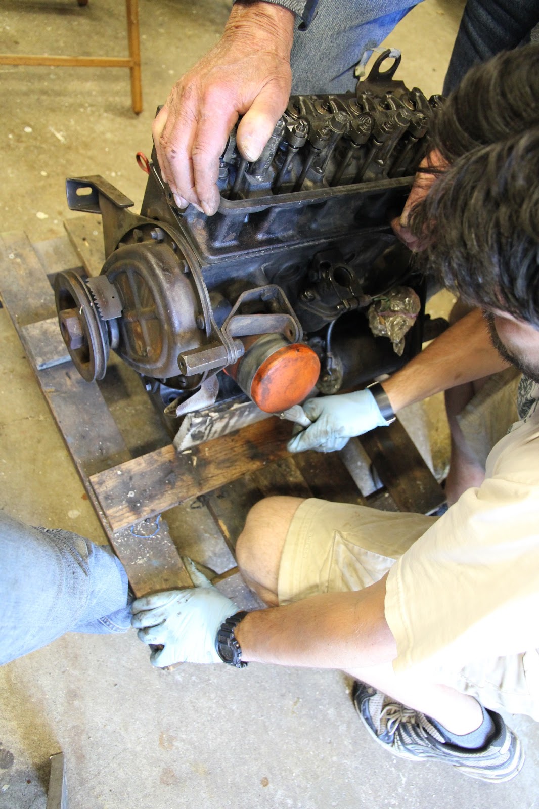
Wednesday, July 17, 2013

Carburetor Cleaning

Forward: Learning the following information proved useful a few weeks later as Chris and I found ourselves helping a friend fix up his boat engine during a week long stay at Lake George.  Long story short, the engine to his boat was running roughly and stalling at low RPMs.  Cleaning up the carburetor fixed this and we saved the vacation (not really, but people were really happy to use the boat during the vacation).


Since the gaskets on the carburetor looked new and thing looked mostly in good condition, we only did a basic cleaning on the carburetor.

Step 1 - Removing the idle trim screw.  Before removing the screw, count how many turns it takes to tighten the screw down to where you just start to feel resistance.  In our case, it was 1.5 turns.  (This information is used later when installing the screw.)  After you get this information, unscrew the screw.


Step 2 - Clean the screw and carburetor.  Take some carburetor cleaner and spray the end of the screw clean (notice how black it is in the picture above) and spray the the hole where the screw once was (give it a good spraying).

Step 3 - Spray clean.  To help clear out the carburetor cleaner that was just applied, spray compressed air through the carburetor screw hole.

Step 4 - Screw in the screw.  Screw in the screw all the way back in (until you feel resistance) and then loosen it back out based on the number of turns from step 1.

A New clutch

Although the clutch appeared to be in good condition, we had purchased a 3-in-1 clutch kit (release bearing, clutch cover, and clutch disc) a while back and figured we would replace these parts while we had easy access to them.  Installing a new clutch was pretty straight forward and replacing the release bearing was also straight forward after Fred realized he had a few pullers stowed away in a box in the garage. 

To replace the release bearing in the bell housing, the release bearing mounting hub was removed from the clutch lever and a puller was used to separate the release bearing from the release bearing mounting hub.  The trick to using the puller was putting the unit in the vice and placing a socket inside the bearing (socket diameter was smaller than the bearing but larger than the mounting hub diameter).  The socket provided something for the puller shaft to press against. (Sorry, I forgot to take pictures of this.)

To remove the clutch cover and clutch disc, 6 bolts were unscrewed from the clutch cover and the whole unit came off.

Replacing was the opposite of removing, but before tightening the bolts down, we had to make sure the clutch was aligned.  To do this, Victoria British sells an alignment tool that is a shortened model of the transmission input shaft.  You put the tool through the center of the clutch and make sure everything aligns accordingly before tightening down the bolts to spec....

...but since I did not get the alignment tool (I thought I purchased one, but actually did not), we used the old fashioned method.  We removed the bell housing from the transmission and Chris put the transmission shaft through the clutch and held up the transmission while I tightened down the bolts. Removing the bell housing was a necessary step so that we could get access to the clutch cover bolts while the transmission shaft was put in place for alignment.


...nice, shiny new clutch cover and disc.

Sunday, July 7, 2013

Checking the Oil Pump and Valve Train

With the oil filter in place, we could now add some oil and give the engine a few spins.  The main reason for doing this was to make sure the oil pump was circulating the oil properly.

After filling the engine up with oil so that the oil level read at least "min" on the dipstick, we jumped the starter to Chris' truck battery and let the engine spin a bit.  Soon we realized that the oil pressure switch was not present and oil would spurt out this hole while the engine was running. (I wish I had gotten a video of this.)  As a quick fix to this problem, Fred plugged up the hole with a #2 pink pencil.
Oops...need to plug up this hole.

In the picture below, you can just see oil start to spurt through the rocker assembly.

The engine in action...

Wednesday, June 26, 2013

Oil Filter Fiasco

Maybe "fiasco" is a bit dramatic, but the oil filter replacement ended up taking an hour, which is about 55 minutes longer than what it should have been.

To start, the oil filter was removed using an oil filter strap wrench...straightforward - no issues here.

When we went to put on the new oil filter, we noticed that it did not have a screw mount to attach to the engine.  (See below, parts don't fit.)


Then we thought, "Well, maybe we needed to remove the screw from the old filter."  So Fred tried freeing the screw using the 2-nut removal technique.

No luck here, so maybe some better access to the oil filter is needed.  To do this, Fred sawed off the oil filter with a circular saw.

Still no luck removing the screw, so a little heat action was applied to see if this would help loosen the screw.

Being an oil filter, there was some oil leftover and this caught fire. (we put out the fire in the nearby water bucket)

What finally did the trick was grinding the screw out from the inside of the oil filter and then using a hammer to tap it out.
Finally removed
While Chris and Fred were examining how to attach the newly freed screw and whether or not the threads survived the extraction process, I decided to review the parts I had bought for this trip to New York - some manifold clamps, gaskets, a fan belt...  Then I took a closer look at the fan belt to read the packaging information and then I hear "clink clink clink" (the sound of metal falling onto the floor).

Hmm...what's this that fell out of the fan belt? (I asked myself)  It turns out that I had ordered an oil filter adapter screw but that it had gotten stuck during shipping inside the fan belt packaging!  We had the part all along!
The oil filter (left) and critical part to oil filter installation (right)

With this new screw in hand, the oil filter installation took less than 1 minute to screw on...but with the time spent trying to salvage the old screw mount, we spent about an hour trying to install the oil filter.  This was not one of our finer moments of the weekend, but I do need to applaud our determination to make things work and thank Fred for his patience and hard work.

Tuesday, June 25, 2013

Back to New York

We went back to New York this past weekend to finish restoration of the engine.  First thing we tackled was replacing the engine head back in place and adjusting the valve spacing (rocker arm clearance), but before doing this, we marked the crankshaft pulley where pistons 2 and 3 were at top dead center (the pulley already had a marking for where pistons 1 and 4 were at top dead center; the marking for pistons 2 and 3 was opposite of 1 and 4).  (These markings will be used later).
Crankshaft pulley marking

Dropping the rocker shaft in place
After tightening everything down to the torque spec, the next step was to check the valve spacing clearance.  To do this, we rotated the flywheel to get the pistons adjusted at top dead center of the compression cycle (markings from the step above helped here).  Then the valve spacings of the top dead center cylinders were adjusted to spec.

A feeler gauge blade of  .010" (the Haynes manual spec for valve clearance) was slid into the spacing and the individual rocker arms were adjusted by tightening the ball pin. This was repeated 8 times for each rocker arm (flywheel rotation was done according to which valves we were working on).
Adjusting the valve spacing
Next up, we checked the oil pump circulation and that required installing a new oil filter first.  This turned out to be more of an ordeal than it should have been...so I will save this for a separate post.

Tuesday, June 11, 2013

Part 10: Re-installing the Pistons


To install pistons, a ratchet type piston ring compressor was needed.  Since the rings were brand new, the rings stuck out of the pistons a bit.  The ring compressor wraps around the piston and squeezes the rings into place.


But first we dunked the piston in engine oil, to make it was properly lubed before installing (oil was also squirted onto the cylinder walls).  Then the piston compressor was attached to the piston and the piston was positioned over the cylinder (make sure the arrow on top of the piston points to the front/fan of the engine - piston installation direction matters).  The wooden end of a hammer was used tap the piston back into the engine.

One thing to note...make sure the piston compressor bottom lines up flushed with the piston bottom.  In our first few attempts, the compressor was not perfectly aligned and the ring would slip out underneath before we could push the piston through the engine.


To install the pistons we had to turn the engine on the side to reattach the connecting rods.  The big-end bolts that held the connecting rods in place needed to be torqued to 40 lbf ft.  Cylinders 1 and 4 could be installed at the same time since they rotated on the same crank shaft cycle and cylinders 2 and 3 could be installed together on the opposite cycle of the cam shaft (turning the fly wheel rotated the cycle and raised and lowered the pistons).
The dogs are helping Chris and Fred with piston installation.


This pretty much wrapped up a weekend worth of engine rebuilding.  After the pistons were re-installed, the oil pan was attached and that's how we left for the weekend.  It took 2.5 days (1 day = 9AM - 5PM with a break forlunch) of effort amongst 3 people to get to this point.  Fred's assistance with this really sped things up with his wealth of knowledge, tools, and everything on hand and ready to go.  We'll be back to New York mid-summer to finish the rest of the engine restoration.


Part 9: The Mystery Behind the 3rd Cylinder Has Been Solved!!!

Back in August 2010, I had posted the results of our compression testing.  No matter what we did, the 3rd cylinder always reported abnormal results.  Well, I am pleased to announce that we believe we know what the cause is...the top piston ring of piston 3 was stuck.  

Removing the piston rings on the first pistons were pretty straight forward.  Dig you nails into the gap and pry off the ring.  With the 3rd piston, however, the top ring was stuck in its groove.  The ring would not spin in the groove or dislodge easily (other rings moved freely in the groove).  It took Fred a while to finally pry it loose.

The guess (not an expert opinion) was that the stuck ring caused the 3rd cylinder/piston to not have good compression.  (The stuck ring impacted the travel of the piston in the cylinder.)

After removing the rings, we snapped a few old rings in half and use these as a tool to scrape out carbon residue built up in the ring grooves.  The piston heads then went through some wire brushing to make everything nice and clean before installing new rings. 

For the bottom ring, installation order matters. The waffle ring is installed first and then the top and bottom rings are installed.  (There are slight grooves in the waffle ring that the outer rings sit in.)  This is useful to keep in mind when removing the bottom ring as well - take the outer rings off first.

Like new...